New Features in pCon.planner 7.2Print
New Rendering Process for High-Quality Images
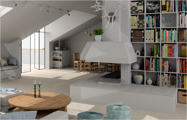
Is it possible to create superior images without professional knowledge? With the additional rendering engine in pCon.planner 7.2, you can create beautiful illustrations directly from your active work area.
The new image calculation tool is simple to use. Without the necessity for enhanced manual system settings and light-ing, great results can still be achieved. To start the continuous rendering process, click on the Start Rendering button. Your finalized rendering can then be saved as an image file.
The new rendering process is also interactive. This gives you the ability to change or adjust the camera view while the rendering is taking place. Once an adjustment has been made, the process continues from the new perspective. In addition, you have the ability to change the current viewport and continue planning. Doing so has no effect on the rendering taking place.
The new renderer is located in the Beta Functions tab on the Ribbon.
Please note: The new rendering engine in pCon.planner is currently in beta status.
|
Rendering created with the new interactive rendering engine in pCon.planner 7.2 |
True-to-Scale Printing with the New Print Preview
With the new printing tool, your can present your planning details in true scale or provide your clients with an overview of your plan's furniture arrangements.
By clicking on the Print Preview button under the Presentation tab, you will see a preview of the active work area content. Under the Properties Editor, you can set the desired Scaling for your printout. Alternatively, you can interactively zoom into a desired viewing area. The Render Mode, Format of the paper, etc. are also easily controlled using the Properties Editor.
Title blocks with information about the project and planning, also known as a Stamp, can be easily added to the printout. The same applies to your logos.
Vector printing of a viewpoint is also available for various display modes. With this, the quality of the display remains the same regardless of magnification level.
|
Print Preview of a print page created in pCon.planner |
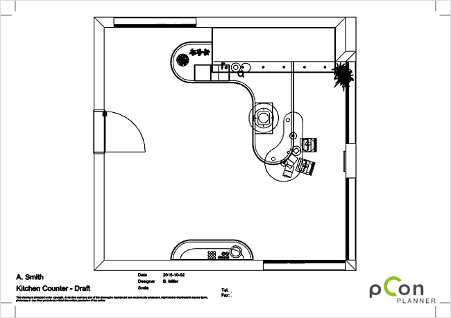
Print Preview can be opened by clicking on the appropriate button in the Presentation tab.
Creative Design: Drawing and Construction Tools in pCon.planner
From furnishing with cable bushings to custom-fit designs for tabletops or individual solutions for room features, when it comes to the implementation of customized planning ideas, you can rely on the pCon.planner Construction tools.
The foundation for the construction of design concepts or everyday objects often starts with 2D Drawing Elements, and these have continued to grow: New tools and functions within pCon.planner now allow for more flexibility when it comes to sketching and planning.
|
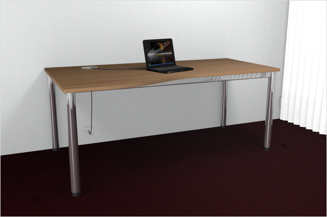
Free form table created with the drawing elements and construction functions in pCon.planner 7.2 |
pCon.planner 7.2 offers the following new features for your design ideas:
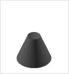
Merging Objects, Creating Intersections, Subtracting from Objects
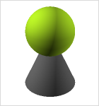
Within pCon.planner, boolean operators can be used for various 2D surfaces and 3D objects. With Subtract, you have the ability to remove one object from another. Intersect allows for the superposition, or overlapping, of at least two elements. The Merge function creates a new object from two planes or shapes that are touching one another.
All options can be found in the Edit tab in the group Construction.
|
|
|
|
Initial state |
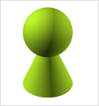
After subtracting the sphere |
After merging the two objects |
After creating an intersection |

Complex Extrusions with the Follow Me Tool
This tool helps you guide complex extrusions along a particular path. This can be used for the creation of baseboards or cable ducts, for example.
The Follow Me tool can be found under the Edit tab in the group Construction.
|
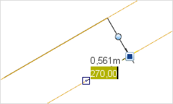
Follow Me Tool – Extruding a circle along a path – left: initial state; right: result |

Freehand Function, Circular Sectors and New Arc Tools
Let your creativity run wild: Curvy lines can be quickly created with the Freehand tool. Subsequently, you can also adjust the curvature and alignment.
With this, you can create a curved countertop as easily as if it were on the drawing board. Cable bushings and organic shapes can also be constructed with the Freehand tool.
|
Editing a freehand line – curvature and orientation will be adapted for a particular point |

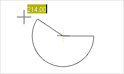
Running drawing of a Pie; Inputting the encompassing angle |
With pCon.planner 7.2, you can now draw a Pie (circular sector) in next to no time. To do so, set the middle point of the circular sector, draw the radius, and with two clicks, set the start and end point of the corresponding arcs. This can be helpful to attach a custom-made tabletop on an existing table, for example.
|
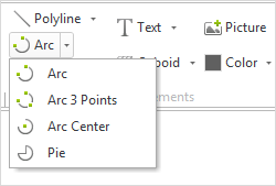
Opened menu showing the various Arc options |
Taking the place of the conventional Arc function are three new tools: Depending on your requirements, with pCon.planner 7.2 you can set an arc using two end points, 3 points or a middle point, radius or angle. You can learn more about creating and editing 2D Drawing Elements in the corresponding chapters of the online help center. |
The new Drawing Elements can be found under the Start tab in the group Drawing Elements.
New Features for Polylines, Polygons and Line Tools
Drawing process for a polyline – The angle of the line can be entered while drawing, ledger lines then appear for the parallel alignment of the lines |
New drawing processes ensure the exact placement and length of lines or polylines: Now you can directly give length and angle specifications for every line segment. While drawing polylines, ledger lines will appear, allowing you to easily align with the parallel or orthogonal lines.
|
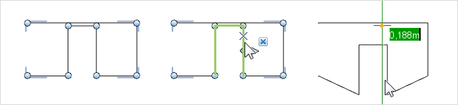
For the editing of polylines, new options are now available to you: Every line segment and node can be edited individually. With multi-selection, you can choose several points or line segments in order to collectively move them. This ensures that the lengths and arrangements remain the same while the remaining elements are adjusted accordingly.
If you draw several new lines at the end of a Polyline, they will be directly connected. In the same way, if you drag the endpoint of an existing Polyline to the endpoint of a second, the will automatically be combined into one element.
|
Editing a polyline, including multi-selection – selected lines (middle) are moved together; the result is on the right |
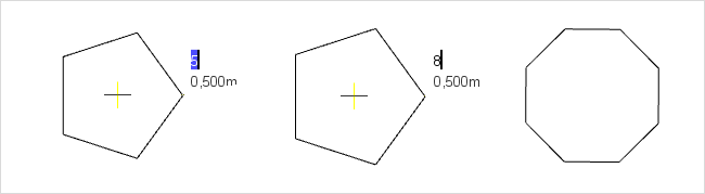
You can draw polygons faster now, as well: The number of sides is immediately entered during the drawing process.
|
Inserting a polygon; Changing the number of sides from five to eight |
Polylines and Co. can be found under the Start tab in the group Drawing Elements.
Sharing CAD Models Online with Partners and Customers
Let your partners and customers take part in the planning process. With the new feature Share CAD Model, you share details, individual furniture items and complete plans online. The service is based on connection to a cloud service. Within the Sharing Settings dialog of Share CAD Model, you can choose from several providers for CAD model sharing.
If you would like to share objects with others, select them within your plan. In the dialog Share CAD Model, you have the option of copying the model link to the clipboard, sending the link via e-mail or displaying the object directly in the browser. The model is then continuously accessible online.
Once the object is shared, it can be passed on to other potential viewers. You have the ability to zoom in, rotate and change the point-of-view of the shared model. This allows your customers and partners to have a quick overview of your proposed plan.
Please note: Specifications for model quality can be made in Sharing Settings of Share CAD Model under the Options tab.
|
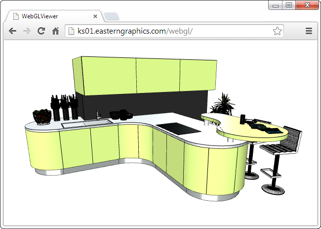
Browser view of CAD Model |
Share CAD Model can be found at the top right-hand corner of the ribbon.
Customizing Illustrations for Real-time Views with Render Styles
With Render Styles you can create individual illustrations for real-time views. With no actual rendering required, you can accomplish high-quality, stylish visualizations for your plans – complete with your logo, individual line styles and color scheme. Render Styles can be used for images in the viewport as well as for Layout pages.
Render Styles can be found under the View tab.
|
Example of a Render Style with logo, alternative line styles and shaded background |
Importing building models in IFC format
The ability to fulfill the BIM standard is made possible with the option to import IFC files. The BIM concept allows for the program application and trade-spanning digital characterization of building models. Files can be imported using the application menu.
Exporting Common Geometry Formats and Vector Graphics
With pCon.planner 7.2, you can now export geometric data in DAE, SKP, OBJ, as well as FBX formats. Vector graphics can be exported in SVG, EFM and DWG formats. Export options can be found in the application menu.
Simple Drawing of Walls on Top of Floor Plans
With the Floor Plan tool, you can work with room shapes and wall thickness: By inserting a plan and using the Floor Plan function, you can manually trace the outline of the walls and the walls will be generated automatically. The Floor Plan function can be found under the Start tab in the group Room Elements.
Space Management: Dividing Spaces and Inserting Room information
With the Split Room tool, you can divide rooms into various functional spaces or work areas. The Room Stamp will then measure and display the circumference and area of any closed space. Both tools can be found under the Start tab in the group Room Elements.
Layer Management for Work Areas and Overall Planning
The Layer Dialog and Layer Filter can be used either globally or for each individual active work area. With the Filter Editor, you can create your own layer filters as well as their content. The Layer Filter can be found under the Start tab in the group Visibility; the Layer Dialog is available on the Toolbar.
Copies Connected to the Original
The Reference option creates copies of an object that are linked to the original object. If you change the color, material or a feature in the Properties Editor, this action will have a direct effect on all other references. In other words, the modifications are directly transmitted to all other copies, saving you time. The Reference option can be found under the Edit tab in the group Tools.
Feature Transfer with the Properties Editor
The possibilities of the Properties Editor have increased with the addition of fast characteristics transfers: With Drag&Drop, you can simply drop properties into the property container. From there, they are assigned to other objects. The property container and its functions can be found on the lower edge of the Properties Editor.
In pCon.planner 7.2, a further insert point can be defined for each object, which is (as an alternative to the existing points) selected during object insertion. The Insert Point tool can be found in the group Tools (Edit tab).
Defining Line Styles for Drawing Elements
Highlight Drawing Elements on plan printouts and images: For both prints and real-time illustrations, the view options can be determined for line type, scaling of line segments and line thickness. Settings can be customized in the Properties Editor.
This option can be used to shade drawing elements and closed polylines. Hatch can be found under the Edit tab in the group Tools.
New Types of Dimensioning and Editor for Dimension Styles
More options for standardized dimensioning: Rotated Dimension can be used for measurements with fixed angular dimensioning. The dimensioning of angles is also possible now. With the Dimension Styles editor, you can also deter-mine the look of your dimensions.
Options can be found under the Edit tab in the group Dimensioning.
Creating and Using Drawing Templates
Give your plans a uniform appearance: Templates are drawing files in which certain settings and objects – for example Dimension Styles or floor plans – are included. You can create your template directly in pCon.planner and leave them in DWT format for future use. The function to open templates can be accessed from the application menu.
Simultaneously Opening Multiple Plans
With the ability to open multiple plans at the same time, you can easily compare plans or quickly copy content from one file to another.
Free pCon.planner in 64-Bit Version
pCon.planner 7.2 is now available in a full 64-bit version. This is a standalone version that can be installed and operated simultaneously with the conventional 32-bit version.
The 64-bit version allows you to manage and use more working memory. This is especially advantageous for memory-intensive operations, such as loading, editing, printing and saving extremely large plans. As a result, the stability of the application is significantly higher.
To benefit from the 64-bit version, you need at least 4 GB of RAM. However, we recommend the use of 8 GB of RAM.
Enhanced Placement for Wall Elements
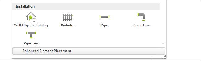
Customized dimensions for wall elements are just a few clicks away. With the help of the Enhanced Element Placement option, you can determine the width and initial characteristics when actively inserting windows, doors, etc.
Enhanced Element Placement can be found in the Room Elements dialog, Start tab.
|
Enhanced Element Placement option, Room Elements Group, Start tab |
|
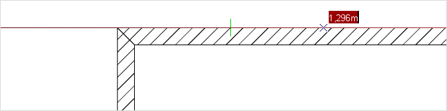
Inserting a Door: Determing the starting point and entering the desired width |
|
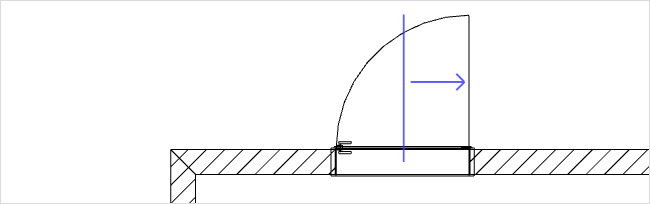
Determining the opening direction of the door during placement |
The updated tooltips will provide you with a quick program orientation. This briefly describes the functionalities of the elements in the user interface.
Hover the mouse pointer over a button or function without clicking. After a short time, a description of the function will appear. Tooltips are available for the application menu, the ribbon and all other toolbars. Even complex settings within dialogs have their own tooltip.
In the Print Preview of pCon.planner 7.2, you can choose from the drop down menu whether you’d like to print a plan as an image or a vector graphic. The Print Mode option can be found in the Properties Editor. The image option is predefined.
If you change the height or width of a wall in the context menu during the drawing process, these parameters with be used for future walls. Previously, the parameters given in the context menu were only applied to the selected wall.