New Features in pCon.planner 7.3Print
Create Media with Improved Options
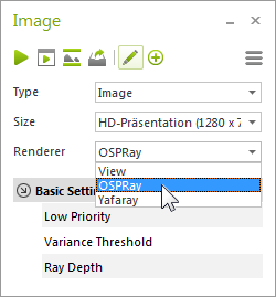
Image Rendering: one Dialog, three Renderers In pCon.planner 7.3, you will now find all rendering options in one place. You can render photorealistic views using the Image button found under the Presentation tab. Choose from three different renderers and their respective settings. With this, you can create the exact image you need for your particular purposes. The OSPRay renderer is no longer in Beta Status, and is fully integrated as a rendering tool under the Presentation tab. |
|
Selecting a Renderer from Image dialog |
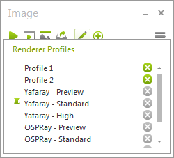
Are you looking to get started without manual default settings? For image rendering, you can simply choose from several prepared profiles. Are you a rendering pro and would prefer to use your own settings? You can save individual settings as your own profile. You can then select them from the Profile drop-down menu. NOTE: Under Type in the image dialog, you can choose an image variation: create standard images, panoramas or multi-content pictures. |
|
Selecting a Profile from Image dialog |
The Video Button
Video, also found under the Presentation tab, will open the dialog for video rendering. Here you will find all of the necessary settings for generating a high-quality video sequence from your own animations.
Improved settings for the OSPRay Renderer
The OSPRay Renderer did not just move to the Image dialog, it also has new settings as well.
NOTE: If you would like to use OSPRay in pCon.planner, please ensure that your CPU uses at least SSE4.1 An operating system of at least Windows 7 (64-Bit edition) is also required.
For an even more realistic image, integrate a panorama into your rendering. In the area Background of the improved OSPRay render settings, select the Panorama option and upload a panorama image into your plan. This will give your rendering an appealing setting.
|
Rendering including spherical panorama als background (Panorama: iStock.com/mihtiander) |
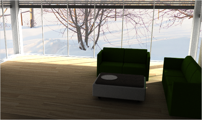
NOTE: In order to avoid perspective errors, please use a spherical panorama as background image.
For extra-realistic lighting, HDRI Light is available. When this option is enabled, upload an HDRI Image (High Dynamic Range Image) in pCon.planner. This image will be used as an invisible background light source for the scene and the lighting will be adjusted to the lighting conditions of the image.
Beautiful prints and PDFs: All editions of pCon.planner have a uniform printing process. With the new version of pCon.planner, lines are printed as clear as if they were on the drawing board – regardless of the scale and without additional settings.
The new printing process works for all render modes and render styles.
|
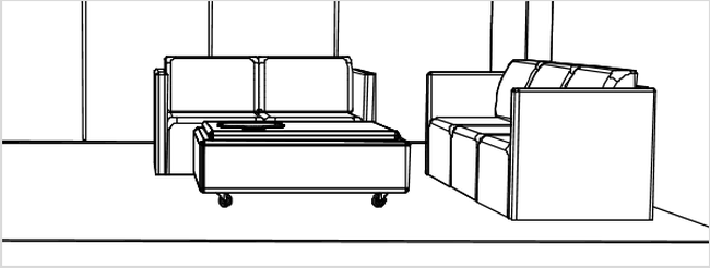
PDF print using the new printing process (High Quality Printing activated) |
The process is based on a combination of techniques: Visible lines, edges, points, hatches and texts are based on vectors. In vector printing these elements are sharp, even when magnified, keeping unsightly jaggies out.
|
Detail from PDF print above using new printing process – magnified to four hundred percent |
Colors and textures are also included in the prints. This is important for images without enhanced edges (for example in Realistic render mode).
Selecting a Printing Process
The new printing process is preset in pCon.planner and will automatically print in higher quality. If you would like to avoid vector printing, you can simply disable it. The print will then be of conventional quality. This way, the file size of the PDF will remain smaller and printing will save memory.
|
|
||||||||
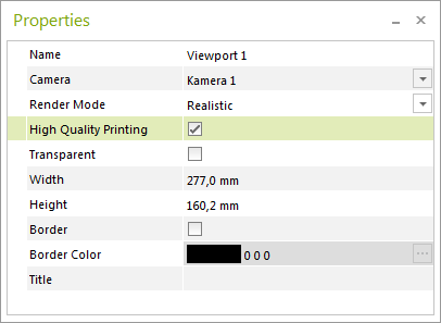
High Quality Print option in Properties Editor |
|
Print and PDF Settings
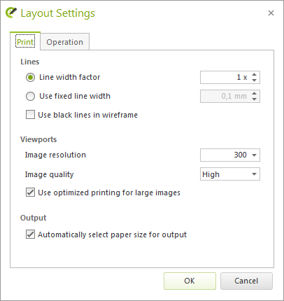
For the lines and elements created in vector print, the settings Line width factor and Use fixed line width are available. You can find both of these in the Layout Settings (Print Preview, group Page, Options arrow):
|
The Line width factor is multiplied by the set line width for lines, edges, drawing elements and hatches. Differences in the line widths remain.
Use Fixed line width determines a uniform width in millimeters for all lines, edges, drawing elements and hatches in the viewport.
|
||||||
Settings for the display of lines in print and PDF |
|
NOTE: With the increase in quality from the new printing process, the previously necessary Viewport output optimization option has been removed.
Simple and Elegant: A new Render Mode
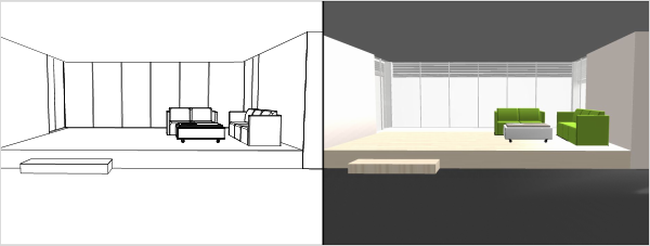
pCon.planner 7.3 provides an additional render mode with a familiar name. The new mode goes by the name Colored. Up until now, a plan in this render mode included colored lines, the color itself and colored textures.
Now, you can switch to Colored mode when you want to display your rooms and furniture with color and enhanced edges. As opposed to textures and multi-colored materials, this mode will display a corresponding color value. The result is a simple and elegant representation.
When preparing printouts or PDFs in particular, we recommend working with the new Colored mode. When it comes to printing, two-dimensional colors often have a more pleasant effect than bumpy textures. In addition, colors look great even in high resolution.
|
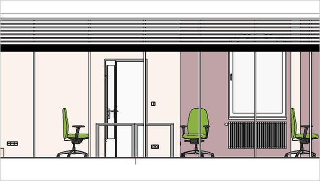
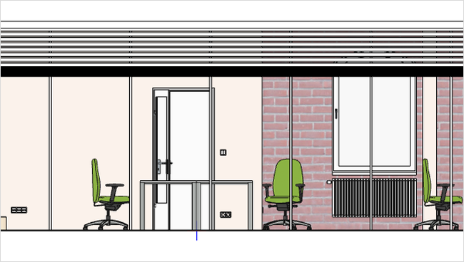
Front view of a plan in render mode Colored |
If you’d like to display lines, colors and textures in the future, simply choose the Textured mode.
|
Front view of a plan in render mode Textured |
Altogether, pCon.planner 7.3 provides a total of 7 render modes. Since each Render Style is based on a stand-ardized render mode, you also benefit from the wide range of choices.
Changing Wall Thickness in a Specified Direction
|
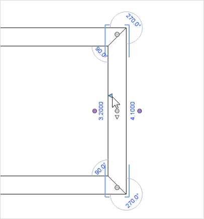
Is your room finished, but you still want to customize the wall thickness? Previously in pCon.planner this could uninten-tionally shrink your floor plan. However, a new wall interactor has solved this problem: With a simple click on the triangle, you now determine where the inner side of the wall should be. The selected wall side will hold its position, even when you change the thickness of the wall, and the inner dimensions of the room will remain the same.
|
Determining the inner side of a selected wall |
|
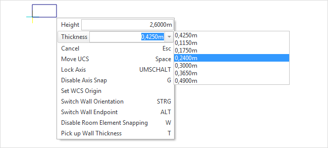
Looking to adjust the wall thickness during the drawing process? Now, there are more options available to you. You can take advantage of predefined values for wall thickness, which have been added to the context menu:
| 1. | Set the starting point and begin to draw your wall. |
| 2. | Right click with your mouse to open the context menu. |
| 3. | Here you will find the input field Thickness. Choose one of the predefined values or simply enter the desired wall thickness. |
|
Selecting a preset wall Thickness from context menu |
The last custom thickness values that you use will then be saved to the list.
You can still retrieve the most recent values from the context menu the next time you open pCon.planner, even if you are working with a different plan.
Disabling Automatically Connecting Polylines
For many use cases, it makes sense to automatically connect polylines. You draw one line, for example, and at a later time draw a second one attached to the end of the first. The second line will then automatically connect to the first polyline, merging the two into one line.
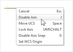
But what if you want to draw a line connecting to another, yet still have it remain a separate drawing element? To do so, simply use the new context menu field Connecting Enabled / Connecting Disabled. By default, the setting is enabled.
|
|
||||
Deactivate connecting of lines from context menu |
|
NOTE: If you always want your lines to remain separate drawing elements, you can also change the default setting:
|
||||||
Edit tab within the Program Settings |
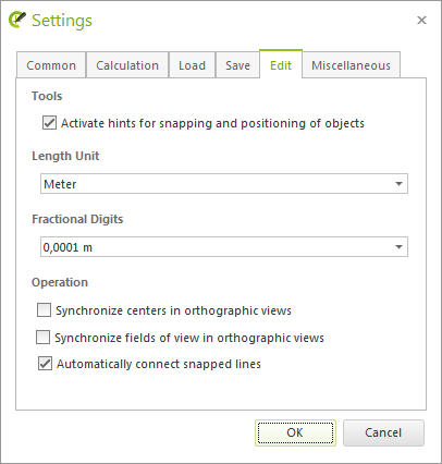
You can also use the context menu field Connecting Disabled when moving polylines. If you have disabled this option, two lines will not connect to one another even if you push them together.
Material Editor: Placing Textures and Normal Maps Independently of One Another
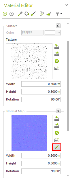
You can expect an improvement when using the Material Editor. Width, Height and Rotation of textures and normal maps of a material can be positioned individually, or can be edited all together. The normal map is initially linked to the values of the material texture: Changes to the texture will be inherited. If you would like to adjust the position of the normal map independently from the texture, click on the pencil icon for the normal map. The input fields will then be available for you to individually position the normal map.
|
|
Material Editor: editing surfaces |
pCon.planner 7.3 supports SketchUp 2016. When exporting geometrical objects in *.skp format, an additional export dialog will be available. Here you can choose from the current or an older version of SketchUp for the export of 3D objects.
The new program version improves your vector graphics. Through the use of a new procedure, the file size as well as the amount of memory used during the export has also been reduced.
From this point on, lighting your plans will be much simpler. Previous default lighting has been replaced with global background lighting. This lighting is active by default and works to produce uniform illumination throughout your plan.
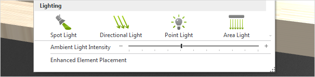
Now, lighting fits to your needs much easier: with slide control (found under the Start tab, Room Elements menu), you can determine how bright your plan is. You do no longer need to input light intensity for standard lighting via the Properties Editor.
|
Setting Ambient Light Intensity: Lighting group, Room Elements menu, Start tab |
With background light you will have the optimal lighting for your renderings. The new lighting affects the display in both Shaded and Realistic mode.