New features in all versionsPrint
New architectural elements: pipework
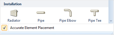
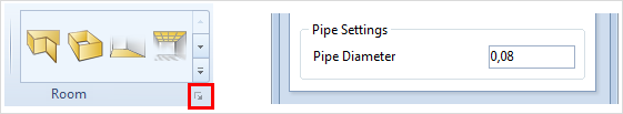
In many industrial buildings and other spaces used for industrial purposes, pipework plays an important role. To take some examples: it is an essential part of production systems which are dependent on compressed air or in gas supply systems used in operating theaters. The package of pCon.planner 6.7 architectural elements has therefore been extended. There are three pipework elements which will enable a simple installation design to be created.
|
|
|
Using lines to create a basic sketch
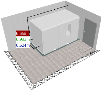
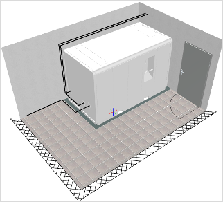
There are two steps in the production of a pipework installation design. First, the drawing tool is used to create the simple lines. These are the basic sketch and will make the manual positioning and alignment of the pipe elements easier in the second step. The example below will illustrate this.
|
|
Using the line drawing tool |
Final basic sketch for the pipe installation |
Positioning pipe elbows and pipe tees
When the basic sketch has been produced, the second step is to position the elbows and tees along the lines that have been previously drawn. To do this you need first to set the diameter of the pipes for the particular case in the Room Settings dialogue.
|
To place the elements correctly, it will first be necessary to put elbows and/or tee pieces at the corners and/or intersections of the intended pipework system. There is a special positioning mechanism in pCon.planner which makes this easier. It is activated automatically when an elbow or tee is selected:
|
|
|
|||
1.) |
The elbow is attached to the mouse cursor at its base point. Position it at the intersection of the two guiding lines and confirm with a click. |
2.) |
Now set the first directional point by clicking onto the line itself or the end of the line. |
3.) |
The next step is to set the second directional point. The elbow will then be turned. |
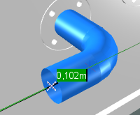
Adding to straight pipes
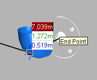
The last step is to complete the straight pipes. Both elbows and tees have special snap points at the center of their end openings to make the correct positioning easier. The straight pipes are then simply drawn by connecting the two snap points:
|
|
|
|||
1.) |
Place the cursor on the end point of the guiding line or on the center of the elbow or tee pipe element. Confirm the selection with a click of the mouse. |
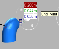
2.) |
Now drag the straight piece of pipe to the next snap point, confirming with a click. |
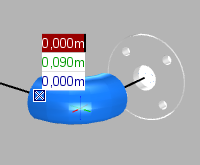
3.) |
When positioning is complete, the next straight piece of pipe is automatically available at the cursor. The process can be continued. |
Extension to the Array command
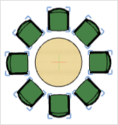
The Array command has been given a new option in pCon.planner 6.7 to enable objects to be set in a circle. In addition, an area can be defined for straight rows, in which a prescribed number of objects can be evenly distributed.
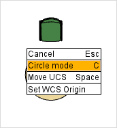
Circular alignment
Circular alignment can be started by means of the context menu or when the user presses C on the keyboard after the Array command is called up:
|
|
|
|||
1.) |
Use a right click to open the context menu and click on the appropriate menu item to start Circle mode. |
2.) |
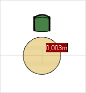
Select the center of the circle you have in mind for the alignment of the objects, confirming it with a left click. |
3.) |
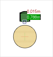
In this third step, you can use a left click to select a reference point on the object to be copied that serves as definition of the cursor position for the ensuing area selection (see also 4). |
|
|
|
|||
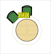
4.) |
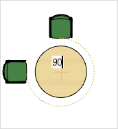
Define the circle or the arc which is to be used for the Array command. To do this, place the object in the position desired or enter an angle (in degrees – a full circle is 0° or 360°). |
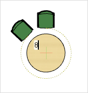
5.a) |
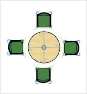
As a last step, you can specify how many objects should be equally distributed in the area selected. Insert the desired number of objects and confirm it by pressing the ENTER key. |
6.a) |
After this the software will place the desired number of objects automatically along the arc you have set or round the complete circle. |
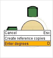
As an alternative to setting a number of objects for uniform distribution, it is also possible to set a distance between the objects by entering an angle in degrees. This spacing taken in account, as many objects as possible will then be distributed around the circle or arc that has been defined. This alternative and how it works from step 5 onwards is shown here.
|
|
|
|||
5.b) |
Open the context menu with a right click on the mouse and select the last of the items, Enter degrees. |
6.b) |
Now enter the desired distance between objects as an angle in degrees. |
7.b) |
The software will place the objects automatically, taking account of the spacing set. |
Distribution in a straight line
The Array command gives another new function in addition to circular alignment. With this, any number of objects can be generated along a notional line and evenly distributed along it. Both the start point and the endpoint can be freely chosen. This is the procedure:
|
|
||
1.) |
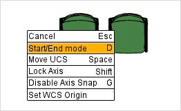
Start the Array command and define the first and second directional points. In the next step the software asks what distance is to be maintained. Now open the context menu with a right mouse click and choose Start/End mode. |
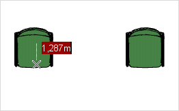
2.) |
In the next step you can define the end point of the area within which the objects are being set out. Move the cursor to the desired position and confirm with a left mouse click, or use the keyboard to enter the distance between that position and the start point. |
|
|
||
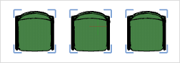
3.) |
Insert the number of objects to be evenly distributed within the desired area. |
4.) |
The objects are created and distributed automatically by the software. |

Administering favorites in the Media Browser
The Media Browser ensures you can access the files system conveniently, directly from the pCon.planner. Using Drag&Drop, geometrical shapes can be imported or exported quickly into any designs that are open. In the new version, the tool has been extended to include the administration of favorites, by means of which directories and files can be saved in the form of links. Even faster access to frequently used elements is thus possible.
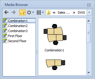
With the new 'star’ icon in the toolbar of the Media Browser you can change between the tree view and the favorite display. Favorites can be created using Drag&Drop from the right-hand detail view to get the directories or files into the favorites window. The favorites will be put into alphabetical order automatically. They can be renamed or, using the DEL key, they can be deleted. A double click enables the favorites to be used. A file will be added to the design which is open. If the double click is on a folder, the folder will be opened and its files shown in the detail view.
|
|
Sample Favorites selection |
Guiding lines for circles and arcs
Notional extensions to arcs
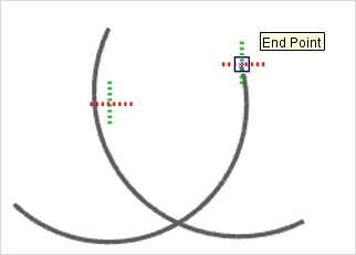
In pCon.planner 6.7, there are additional guiding lines available for circles and arcs. If necessary, a complete circle can be computed to serve as a guiding line for an arc. An example of the use is that intersections of notional arc extensions can be displayed so that objects can be positioned exactly. This is how:
|
|
||
1. |
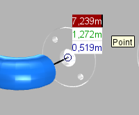
Position the cursor anywhere on the arc. After an instant, the guiding line will be enabled. That is signalled by flashing of the cursor cross symbol. |
2. |
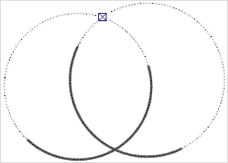
Then the guiding line will be displayed as a continuation of the arc. Do the same for the second arc and you will be able to see their notional intersections. |
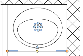
Exact circle intersections
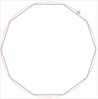
Circular geometrical shapes are made up of small individual line segments. The number of these can be influenced by means of the Tesselation Quality option under general Settings. In consequence, the geometrical shapes are actually only an exact circle or arc by approximation, which means that there may be deviation in the position of the intersection or snap points that can cause errors in the design.
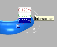
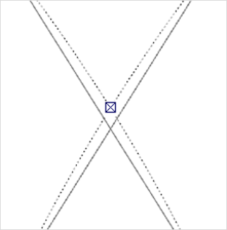
The new guiding lines for circles and arcs will compute intersections which are mathematically accurate. These can be used as an alternative to the 'geometrical' intersections. The guiding lines are activated in a similar way to that in the last example: they appear when the cursor is on the circle or arc and held there for an instant. As soon as the guiding line is active, the intersections taken account of for snapping will be the computed intersections rather than the geometrical ones.
|
|
Example of a circle at very low geometric resolution, with its accurate guiding line enabled. |
Example of the difference between the geometric intersection and the mathematically exact intersection of two circles. |
Additional functions and improvements
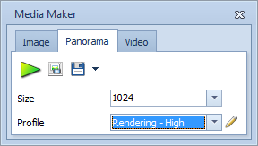
Creating panoramas
The function enabling panoramas to be created is now available in all editions of pCon.planner 6.7. Panoramas are images seen as if from the center of a sphere, so that the user has a 360° all-round view. The Panorama function is to be found on the Present tab in the Media Maker. |
|
Improved compatibility with the DWG format
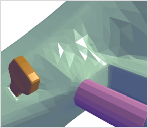
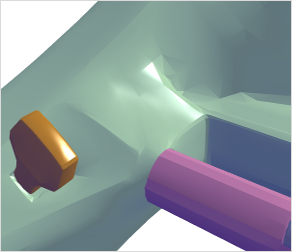
The new pCon.planner 6.7 is distinguished by higher compatibility with DWG format. For example, with Sub-D-Mesh, another type of polyhedral meshes is fully taken account of. Objects which have had their geometry modeled in this manner will now react to face smoothing and will look more realistic.
|
|
Previous rendering of certain polyhedral meshes |
Improved rendering in pCon.planner 6.7 |
In addition, lines and circles from DWG-type drawings that were created with software systems besides pCon.planner can be modified once loaded or imported. The hammer icon can be used to start the editing of such elements. For example, lines in floor plan sketches can be scaled or curved in retrospect. This makes corrections and modifications much easier. |
|
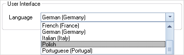
Polish as application language
|
Another application language is now available in pCon.planner 6.7: Polish. This brings up to 14 the number of languages to select from. The option is to be found in the Settings dialogue. |