New Features in pCon.planner 7.2 PROPrint
New Rendering Process for High-Quality Images
Is it possible to create superior images without professional knowledge? With the additional rendering engine in pCon.planner 7.2, you can create beautiful illustrations directly from your active work area.
The new image calculation tool is simple to use. Without the necessity for enhanced manual system settings and light-ing, great results can still be achieved. To start the continuous rendering process, click on the Start Rendering button. Your finalized rendering can then be saved as an image file.
The new rendering process is also interactive. This gives you the ability to change or adjust the camera view while the rendering is taking place. Once an adjustment has been made, the process continues from the new perspective. In addition, you have the ability to change the current viewport and continue planning. Doing so has no effect on the rendering taking place.
The new renderer is located in the Beta Functions tab on the Ribbon.
Please note: The new rendering engine in pCon.planner is currently in beta status.
|
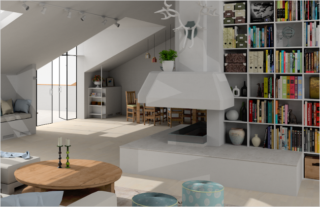
Rendering created with the new interactive rendering engine in pCon.planner 7.2 |
Sharing CAD Models Online with Partners and Customers
Let your partners and customers take part in the planning process. With the new feature Share CAD Model, you share details, individual furniture items and complete plans online. The service is based on connection to a cloud service. Within the Sharing Settings dialog of Share CAD Model, you can choose from several providers for CAD model sharing.
If you would like to share objects with others, select them within your plan. In the dialog Share CAD Model, you have the option of copying the model link to the clipboard, sending the link via e-mail or displaying the object directly in the browser. The model is then continuously accessible online.
Once the object is shared, it can be passed on to other potential viewers. You have the ability to zoom in, rotate and change the point-of-view of the shared model. This allows your customers and partners to have a quick overview of your proposed plan.
Please note: Specifications for model quality can be made in Sharing Settings of Share CAD Model under the Options tab.
|
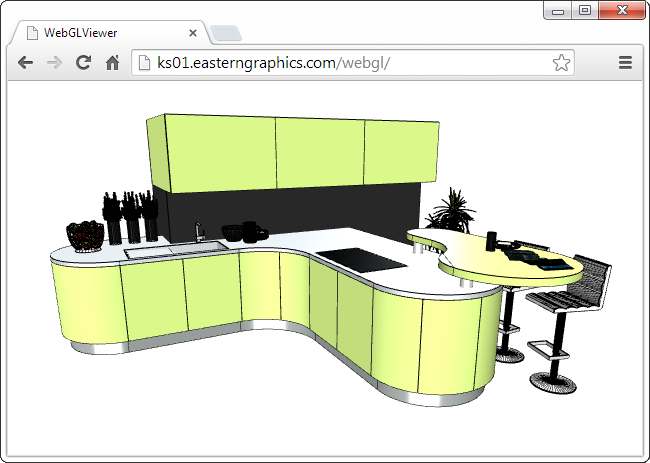
Browser view of CAD Model |
Share CAD Model can be found at the top right-hand corner of the ribbon.
Creative Design: Drawing and Construction Tools in pCon.planner
The foundation for the construction of design concepts or everyday objects often begins with 2D Drawing Elements. New tools and functions allow for more flexibility as well as faster sketching and planning. These innovations complement the already known design options, such as the Follow Me tool or the Merge, Intersect and Subtract options, working together to establish a strong design package.
|
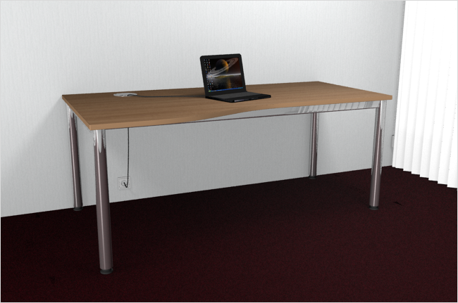
Free form table created with the drawing elements and construction functions in pCon.planner 7.2 |
Freehand Function, Circular Sectors and New Arc Tools
Let your creativity run wild: Curvy lines can be quickly created with the Freehand tool. Subsequently, you can also adjust the curvature and alignment.
With this, you can create a curved countertop as easily as if it were on the drawing board. Cable bushings and organic shapes can also be constructed with the Freehand tool.
|
Editing a freehand line – curvature and orientation will be adapted for a particular point |

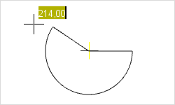
Running drawing of a Pie; Inputting the encompassing angle |
With pCon.planner 7.2, you can now draw a Pie (circular sector) in next to no time. To do so, set the middle point of the circular sector, draw the radius, and with two clicks, set the start and end point of the corresponding arcs. This can be helpful to attach a custom-made tabletop on an existing table, for example.
|
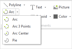
Opened menu showing the various Arc options |
Taking the place of the conventional Arc function are three new tools: Depending on your requirements, with pCon.planner 7.2 you can set an arc using two end points, 3 points or a middle point, radius or angle. You can learn more about creating and editing 2D Drawing Elements in the corresponding chapters of the online help center. |
The new Drawing Elements can be found under the Start tab in the group Drawing Elements.
New Features for Polylines, Polygons and Line Tools
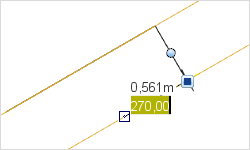
Drawing process for a polyline – The angle of the line can be entered while drawing, ledger lines then appear for the parallel alignment of the lines |
New drawing processes ensure the exact placement and length of lines or polylines: Now you can directly give length and angle specifications for every line segment. While drawing polylines, ledger lines will appear, allowing you to easily align with the parallel or orthogonal lines.
|
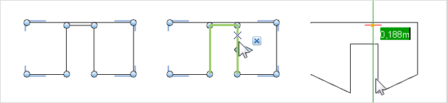
For the editing of polylines, new options are now available to you: Every line segment and node can be edited individually. With multi-selection, you can choose several points or line segments in order to collectively move them. This ensures that the lengths and arrangements remain the same while the remaining elements are adjusted accordingly.
If you draw several new lines at the end of a Polyline, they will be directly connected. In the same way, if you drag the endpoint of an existing Polyline to the endpoint of a second, the will automatically be combined into one element.
|
Editing a polyline, including multi-selection – selected lines (middle) are moved together; the result is on the right |
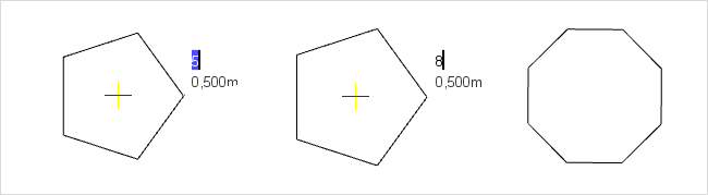
You can draw polygons faster now, as well: The number of sides is immediately entered during the drawing process.
|
Inserting a polygon; Changing the number of sides from five to eight |
Polylines and Co. can be found under the Start tab in the group Drawing Elements.
Assigning and Reading Reference Numbers
Your articles and OFML objects now receive reference numbers directly from the OFML programming. An additional function enables the readout of these reference numbers. To do so, select an item in the plan, for which you would like to know the number. After selecting the appropriate function in the Products Catalog, all numbers associated with that item will be displayed.
The updated tooltips will provide you with a quick program orientation. This briefly describes the functionalities of the elements in the user interface.
Hover the mouse pointer over a button or function without clicking. After a short time, a description of the function will appear. Tooltips are available for the Application Menu, the Ribbon and all other toolbars. Even complex settings within dialogs have their own tooltip.
In the Layout Area of pCon.planner 7.2, you can choose from the drop down menu whether you’d like to print a view-port as an image or a vector graphic. The Print Mode option can be found in the Properties Editor. The image option is predefined.
If you change the height or width of a wall in the context menu during the drawing process, these parameters with be used for future walls. Previously, the parameters given in the context menu were only applied to the selected wall.
With the new version, objects can also be deleted from Layer 0. The layer itself remains intact. Here, a separation between planning mode and Layout Area exists: When deleting objects in the planning area on Layer 0, objects placed in Layer 0 on the Layout Area will not be deleted.