Features and extensions in pCon.planner PRO
Render styles for real-time visualization
In the new PRO version the options available in pCon.planner for visualization in real time have been extended. The Render Styles button placed immediately next to the Render group on the View tab offers the user many ways of creating his or her own style. As in the case of the predefined Render modes1, the personalized styles can be assigned to any viewport. In all but the design area itself, they can also be used in the layout area by being assigned to the different layout views that have been added. However, the render styles are irrelevant to photorealistic rendering.
Creating a Render Style
The dialog is made up of a toolbar and two windows, in the left-hand one of which the styles are shown which have already been stored. The right hand window is the home of the Common and Images tabs. It is with these two tabs that the settings of whichever render style has been selected are made or modified. |
|
Create new render style |
|
Delete selected render style |
|
|
Download style from online catalog |
|
|
Load existing style |
|
|
Save render style |
|
|
Save render style as… |
|
Three Render Styles are shown here in the left-hand window. Some of the settings for the one selected (marked as favorite “own style”) are visible on the right. Styles which have been marked as favorites will be available every time pCon.planner is started. |
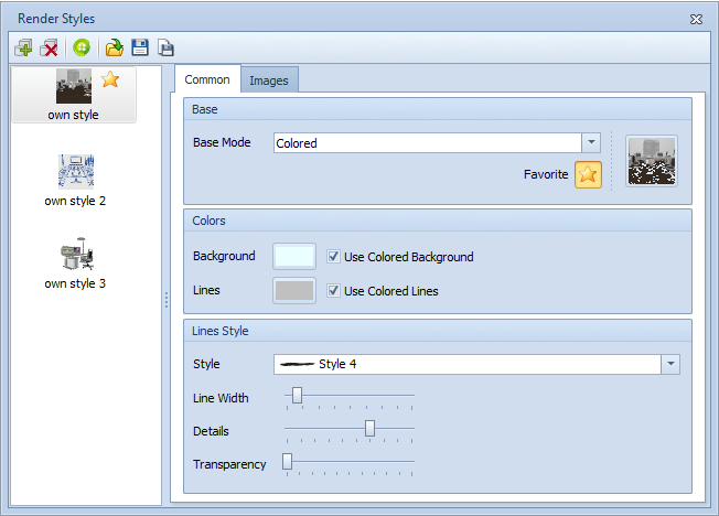
After the first click for the creation of a new style the choice of which rendering mode is to be the basis of the new style must first be made. The options are the familiar modes, Wireframe, Hidden Line and etc.
Colored has two further items - Use Colored Background and Use Colored Lines (the edges of objects). It is possible to configure not only the color of the lines but also their rendering. Here the possible settings are Style, Line Width, degree of Detail and Transparency.
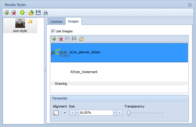
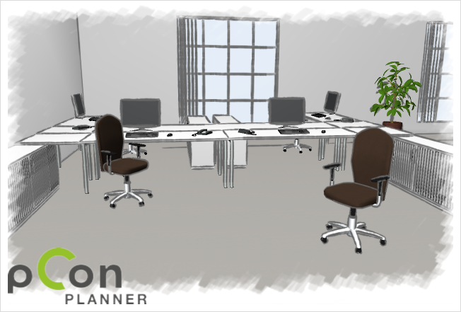
The Images tab is where images or graphics can be inserted into either the background of the design or – this is relevant for logos – into the foreground. The arrow buttons are used to define which object is to displayed in which layer of the rendering style. The Drawing item (which is a representation of the design) is also taken account of during this sorting procedure. The parameters Size, Transparency and Alignment can all be adapted for any images loaded.
|
Two images have been inserted for the rendering style shown here. Both are in the foreground. The logo (file name pCon_planner_660px) has been scaled down to 19% and is positioned in the lower left corner. |
Creating an icon for a rendering style and marking a style as favorite
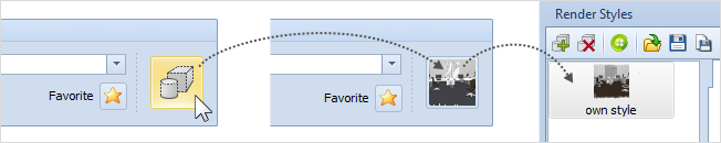
When all the settings for a rendering style have been made, go to Basic Mode area on the Common tab and click on the default symbol for rendering styles on the right. Doing this creates an icon for you representing the style you have just established. The icon will be a miniature version of the current view of your current design.
For a style to appear automatically in the Render Styles dialog as available when a design is opened, it must be marked as a Favorite. When it thus appears, a dialog will open automatically requiring you to save the style. When you have done so – for example, on the local hard drive – and saved the designation Favorite with it, it will appear as available every time you start up pCon.planner.
Using a Render Style
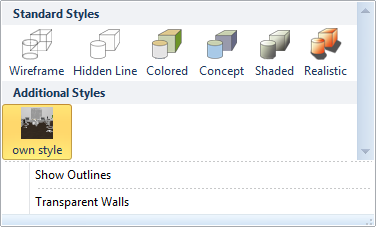
One way of accessing Render Styles is from the Render Styles dialog. Another is to go via the View tab and the Render group and to select the appropriate style from those found there (see screenshot on right). The graphic image below is an example of the effects of the settings saved for the Render Style named “own style” – in the selected view. |
|
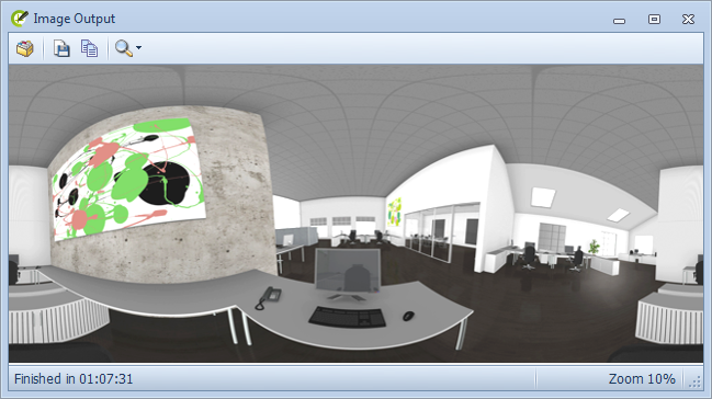
In the Media Maker, there are functions available which do not only create individual images and animations but also spherical panoramas by means of a further button. These are images which are observed, as it were, from the center of a sphere and are perceived to be lying on the inside of this sphere. With the help of a program to render panoramas, the observer can view a scene from where he or she is 'standing', upwards, downwards or by turning on the spot.
To create a panoramic image, a viewing position must first be established in the design. This is best done by using a camera with equal values for Eye Height and Target Height (e.g. 1.75 meters). After this, the height of the image to be computed is set in pixels on the Panorama tab in the Media Maker. The width will appear automatically, always as twice the height.
|
The image output shows the motif projected as a rectangular graphic onto the inside of the sphere after rendering. |
|
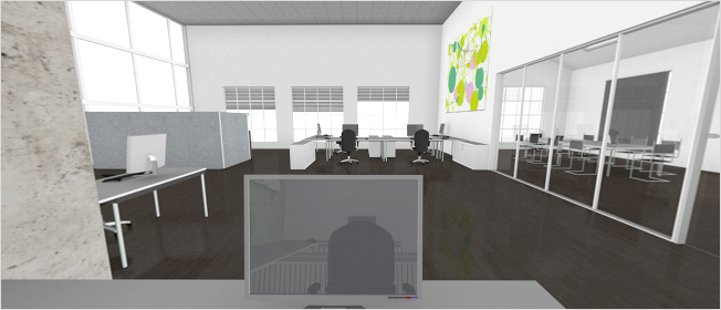
This is the same picture opened in a panorama viewer. The relevant control options can be used to create a 360 degree survey from the viewer’s position. |
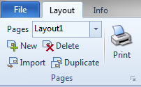
Importing and duplicating
On the Pages tab in the Layout area, there are now the new Import and Duplicate functions. Copies of a page just selected can be made with the Duplicate button – this applies to the entire contents of the page. The Import button allows you to load different layouts (in DWG format) or templates (as DWT) onto the layout area.
|
|
Output from viewports in vector form
The printed output of text and primitive 2D objects such as lines, rectangles, circles and so on from the layout area has always been in vector form. The general advantage of vector graphics over pixel-based – bit-mapped – images (e.g. digital photographs) is that they do not depend on resolution in any way. I.e., even massive enlargement succeeds without loss of clarity, so that the objects will still be rendered clearly and accurately. Another plus is that vector graphics as opposed to bit-mapped graphics in general use up much less memory when included in target files in formats such as PDF.
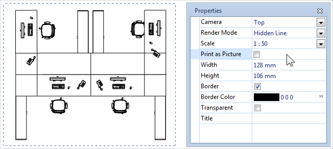
It is now possible with pCon.planner 6.5 to print out the contents of viewports from the layout area as vectors. Depending on which projection has been set, the Property Editor will offer where appropriate the Print as Picture option for the viewport – if this is disabled, the printout will be as a vector graphic.
|
If the Print as Picture item is enabled, the relevant viewport will be printed as a bit-map but if it is disabled, the printout will be a vector graphic. |
The table below indicates which projections and render modes will accept vector printout of viewports.
Projection |
Render |
Top, Bottom, Left, Right, Front, Rear |
Wireframe, Hidden Line, Colored2 |
ISO, Orthographic |
Wireframe |
Perspective, Cameras |
Wireframe |
Footnotes
The expression Render mode is used to describe the various means of presenting realtime visualization of a design. There are six standard modes provided by pCon.planner 6 (Wireframe, Hidden lines, Colored etc.) and these are found on the View tab in the Render group. (Back to the article) |
|
The textures rendered in Colored mode will be converted to homogeneous areas of color for vector printout. (Back to the article) |