Features and extensions in pCon.planner PROPrint
There is now a new tool in pCon.planner 6.6 in addition to the familiar wall drawing tool. This is an easier and more efficient way of drawing floor plans. The method is similar to that for drawing a line. The user first sketches wall plans by dragging the mouse around a floor plan. The areas produced in this way are turned into 3D walls automatically.
The new floor plan tool is found in two places, on the Room group on the Home tab and in the Room group in the Insert tab. It is started with a simple click of the mouse. |
|
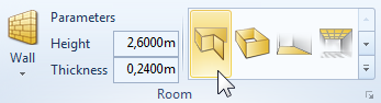
Drawing walls
It is possible to use either a DWG file or an image as the basis of the drawing. Depending on the choice, the user will be helped to produce an exact reproduction in pCon.planner by the snap mechanism, the reference lines and reference points. The tool can, of course, be used without a floor plan template and will then serve as an alternative to the usual wall drawing tool. The two methods can, incidentally, be used in combination to create walls.
|
|
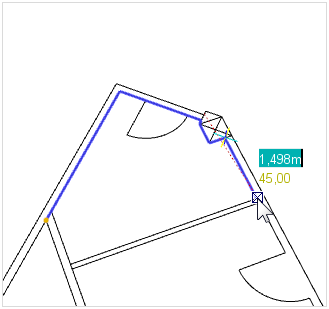
Procedure for reproducing an existing floor plan. |
Finished walls. The interactor points for the wall are visible on the floor. |
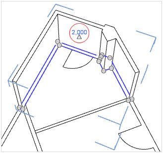
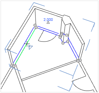
When a line is closed, pCon.planner will automatically create a wall of predetermined height from it. The height can be altered afterwards using the interactor (see red circle in screenshot on right) or using the Properties Editor.
The interaction points enable the shape of a wall to be altered. The relevant point must be clicked on with the mouse and dragged. Pressing Del on the keyboard during the drag process will delete the selected point. Another way of changing the shape of a wall is to insert a further interaction point on a line between two existing points (see image on right). The walls which have been raised with the new floor plan tool can be equipped with wall elements (doors, windows, gates, etc) as well as floors, ceilings and pitched roofs, just like walls drawn in the usual manner.
|
|
Applying materials or colors to wall surfaces
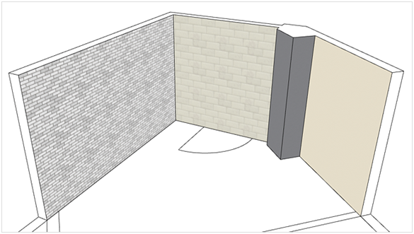
The walls produced with the new floor plan tool consist in areas independent of each other, so that each wall area can be given a different color or material.
Wall hatching
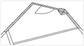
For walls which connect to each other, a uniform 2D symbol will be created. It is also possible to use the Properties Editor to establish different hatch patterns for these walls. If the user disables the 3D rendering, the connected hatch will become visible (see the following image). |
|
Inserting wall elements interactively
It is possible to insert wall elements such as doors, windows and gates interactively in the new version of pCon.planner 6 as well as using the old method.
First set the checkmark alongside Accurate Element Placement in the Room elements group.
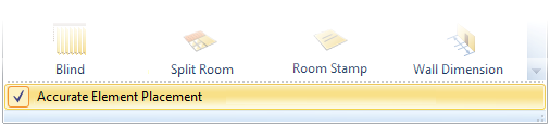
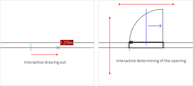
In interactive mode, the origin of the element in the wall is set with the first click of the mouse. Dragging the mouse cursor will set the width and this is fixed with a further click. The user can now change how the wall element opens (vertically also horizontally) by moving the mouse and clicking it at the end.
Reference numbers are the means of uniquely identifying articles and their attached elements in a design. The system is useful, for instance, in assembly and building instructions. The new pCon.planner 6.6 PRO contains the option of allocating a reference number to each item and the number will appear automatically in the design near the symbol for its article. There are also further functions available for alignment and positioning. The reference numbers always accompany the list of articles and any commercial exports.
Manual assignment
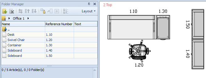
The central tool for the allocation of reference numbers is the Folder Manager in the PRO version. This is found in the Configuration group on the Configuration tab in the Application Menu. It is possible to enter numbers, letters and special characters in the Reference Number column of the table and these will be shown as the reference near the article symbol when Enter has been pressed as confirmation.
Automatic Numbering
Manual assignment of reference numbers is not efficient in every case, especially that of large designs with many articles. Folder Manager therefore offers the user an automatic numbering function. This function works on the basis of selection and thus requires one or more articles or folders to be marked first. Then, the ![]() button in the toolbar of the Folder Manager can be used to call up the automatic numbering dialog.
button in the toolbar of the Folder Manager can be used to call up the automatic numbering dialog.
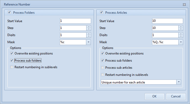
This dialog is divided into two sections to differentiate between reference numbers for folders (on left) and for articles (on right). The table below explains the fields and options.
Option |
Description |
Start Value and Step |
Establishes the start value for the automatic numbering and the interval between one number and the next to be created. |
Digits |
This option enables the reference numbers to be given a uniform length. Any missing places will be padded with zeros. |
Mask |
Special control symbols in the mask allow the formatting of the reference number to be modified. For example, the reference number of the parent element can be inherited by its children or a set prefix or suffix can be attached. Move the mouse over the option field to see a description of the control symbols! |
Overwrite existing positions |
A numbering procedure may require several iterations. This option can be used to control whether reference numbers already allocated are to be overwritten in the next iteration. |
Process sub folders |
This option is used for a hierarchical folder structure to say whether the sub folders and their contents are to be processed during reference number generation. |
Process sub articles |
Hierarchical articles consist in a main article and sub articles. The latter can be excluded or included in the numbering process using this option. |
Restart numbering in sublevels |
This option enables the user to control whether the numbering is to start from the start value within a sub folder. It applies also to hierarchical articles, in which case the numbering will be started a new for the sub articles (such as attached elements). |
Unique or identical numbers |
This option field enables the user to give articles unique numbers or to give identical articles the same number. It is possible at the same time to check for similarity of sub articles in the case of identical articles. |
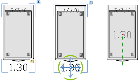
Alignment of reference numbers
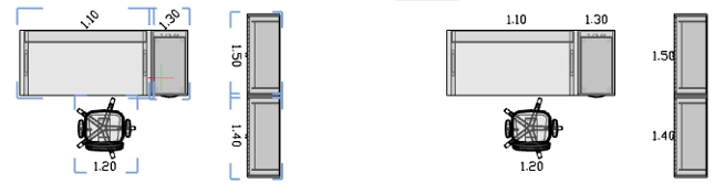
The reference numbers will reflect the rotation of the article and are thus rarely uniform in their alignment, which can impinge on the readability of the design. This option enables the user to align the numbers horizontally or vertically to improve readability. The function works on the basis of selected articles and is to be found on the Configuration tab. |
|

Positioning of reference numbers
When reference numbers have been assigned or aligned, there may be overlapping with other design elements. To get the best readability in this case, too, it may be necessary for the numbers to be repositioned. The options are as follows.
Individual position
If a numbered article is marked, an additional hammer symbol will appear near the reference number. Clicking on the hammer starts the editing.
With the aid of the object interactor, the reference number can be moved or rotated to the position desired.
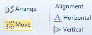
Multiple positioning
|
If more than one reference number are to be edited at the same time, the Move function can be used. When the articles have been marked and the function started, all the reference numbers can be moved or rotated at the same time using the object interactor. |
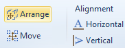
Sequential positioning
|
The third positioning option is to move the numbers in sequence. The reference numbers for the articles marked will be attached to the mouse cursor one after the other and can thus be quickly moved to the desired position. |
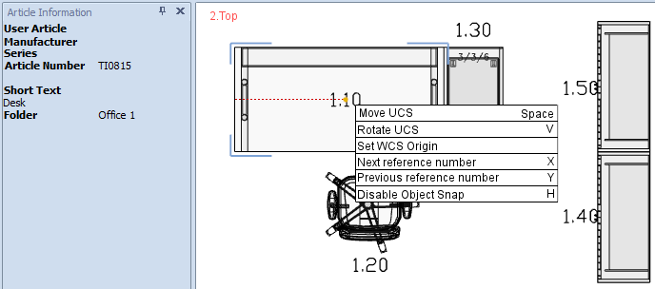
During this positioning procedure, the mouse wheel can be turned to zoom in or out. The zoom will be maintained for the next reference number. Using the context menu (right mouse button), a reference number can be skipped or the previous number returned to. The position of the skipped reference number will not be altered. The Article Information window is an additional help for the task, as it will show the details of the article to which the reference number currently on the mouse refers.
Changing the article configuration
The selected position and rotation of the reference number are stored with the article symbol, as is also the string which has been assigned in the Folder Manager. If the configuration of an article is changed, this string will automatically be deleted. The position and rotation of the reference numbers will remain and they do not have to be readapted when a new string is assigned.
pCon.planner 6.6 PRO has a new tool, the Filter Editor, which enables the user to create individual quick filters for layers. A filter consists in any number of conditions which can be organized in groups and linked by means of logical operations. Depending on how the filters are defined, the visibility of one or any number of layers can be regulated.
The Filter Editor forms part of the Layer Manager, where it can be called up by clicking on the relevant button in the toolbar. The dialog must be closed before continuing with other operations.
Filter Editor toolbar
|
Create a new filter. |
|
Save the changes made to the selected filter. |
|
Duplicate the selected filter with all its conditions and logical combinations. . |
|
Delete the selected filter. |
|
Select a directory in which all filters are stored as files in the form of *.flt. werden. |
|
Apply the filter to the layers in the layer manager. The consequence of this is that only those layers to which the filter conditions apply are shown in the list of layers. This means that the result can be checked even during the creation of the filter. |
|
Delete the filter currently applied to the layer manager. |
|
Enable the visibility of all layers to which the filter conditions apply. Objects on these layers will then be shown in the design area. |
|
Disable the visibility of all layers to which the filter conditions apply. Objects on these layers will then be hidden in the design area. |
Creating filters
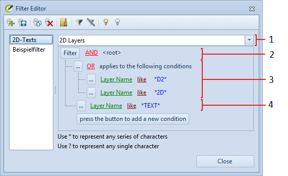
Nr. |
Item |
Description |
1. |
Filter templates |
This field provides templates to facilitate the creation of individual filters. Available are not only the default quick filters and other filter templates, but also the layers of in the drawing currently open. If a template is selected, its conditions will be adopted for the filter currently being edited and they can then be further modified. |
2. |
Filter root |
The filter root is the uppermost layer of the filter. From this layer, a click on the Filter button permits new conditions or groups to be created or the whole content of the filter to be deleted. The logical operator links the individual conditions and groups of the uppermost layer to each other. A click causes the menu of available operators to appear. |
3. |
Groups |
Groups are used to structure filters. They can contain any number of individual conditions or further groups. Clicking the Each group possesses its own logical operator to link together the items it contains. Groups can thus be used to model a variety of logical operations in one filter. A click causes a menu with alternative operators to appear |
4. |
Conditions |
The conditions will set which layers are affected by the filter. If a layer fulfills the conditions, its visibility will be affected by the filter. The conditions refer to the layer names and compare them with the given string (like, not like). The reference string for comparison may be either the full name of the layer or a part of it with wildcards (*, ?). The Edit button can be used for deleting the condition, but also enables other conditions or groups to be added. |
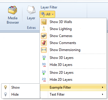
Application of filters
The layer filters created with the editor will be available automatically in the Application Menu among the filter options. This applies to both the design and the Layout area. The user-defined filters are thus complementary to the existing default filters and facilitate efficient showing and hiding of specific layers and their associated objects. The filters are stored in the selected directory in the form of *.flt files. They are thus independent of the drawing and can be exchanged between different systems
|
|
The PRO version of pCon.planner 6.6 offers the opportunity of defining a line style for such drawing elements as rectangles, circles, lines and so on. This line style will be taken account of in the real timing rendering and when the design is printed out. It is also possible in the new version to create hatching and configure this in any way preferred. Both functions can be used in both the planning and the Layout areas.
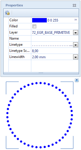
Line styles
In the Properties Editor there are additional features for the drawing elements to help characterize the line style. Linetype: This feature provides a selection of pre-defined line types –dotted, perforated or a combination of both, for example. Linetype Scale: This factor defines the size of the segments of the line type and their distance from one another. A high value should be set for this feature, particularly in large designs, so that the type of drawing element line is also clearly visible. Linewidth: This feature enables the user to set the thickness of the segments of the type of line. The thickness will be dealt with separately in the following section. Please note that the use of the Filled feature will cause the drawing element to change from a line to an area. The line style is now lost and will not be restored if Filled is disabled. To combine a line style and a filling, it is possible to use hatching.
|
|
Hatches
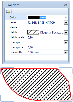
The Hatch tool allows hatching to be assigned to any closed drawing element such as a rectangle, circle, ellipse or polygon or to a complete line. The resulting hatch can be individually edited with the aid of additional features in the Properties Editor as can the line styles. The new function is to be found on the Edit tab in the Tools group.
The screenshot on the right shows the creation of a hatch for a polygon (framed in red). The hatch can be selected independently of the limiting frame and has the following new features. Hatch Type: This feature offers a choice of standard hatch types, including line-based patterns or complete filling. Linetype and Scale: Similarly to line types, line-based hatches can have the type and scale of the lines in the hatch set. The scale factor may need to be adapted to the dimensions of the drawing. Hatch Scale: This factor is for line-based hatches and determines the number of lines and their distance from one another. Linewidth: Again, as with line styles, the feature permits the thickness of the lines to be set. The thickness will be dealt with separately in the following section. |
|
A hatch and the drawing element which serves its limiting frame are automatically associated with each other. If the limiting frame is moved or altered in shape, the hatch will adapt accordingly. However, if the hatch is moved, the association between the two objects will be lost. As a consequence, the hatch will no longer react to moves or modifications of the limiting frame.
Line widths for lines and hatches
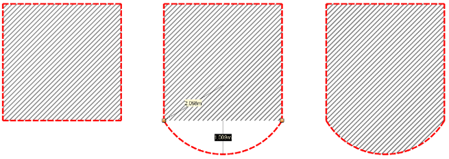
For line types and hatches alike, the thickness of the lines can be set. The line width feature provides a number of predefined values for this. On printout, the mm value set will be printed if the relevant printer settings have been made in the Layout area.
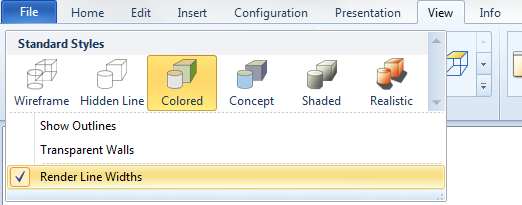
Line widths in real time and photorealistic rendering
If necessary, the line width can be enabled or disabled in real time rendering. To enable this to be done, the new option Render Line Widths has been provided on the View tab of the main menu, in the gallery of render modes. Disabling line width at the design stage may make it easier in certain cases to work with precision.
Printing with line width
The line types for the drawing elements and the patterns for the hatches will be rendered in the Layout area and will be taken into account on printout. Line width will, however, only have an effect in vector print for the view ports . For drawing elements and hatches created in the Layout area, the line width set will always be taken into account. Two further options have also been added to allow the printer settings to adapt specifically to line width in the Layout area.
Layout Print options |
How they work |
Linewidth factor |
This factor will be multiplied by the line width set for drawing elements and hatches, thus affecting the print result. The option will not have any effect on the frame of the viewports. |
Used fixed linewidth |
This option allows a fix line width (in mm) to be set and is independent of the line width already defined for the drawing elements and hatches. The option thus affects both the frames of the viewports and the lines within any stamps. |
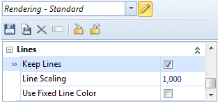
Line width in rendering
Line styles, hatches and the line widths set will also appear in photorealistic renderings. For this to happen, the Keep Lines rendering option must be enabled. The additional Line Scaling option behaves in the same way as does the Linewidth factor described above. |
|
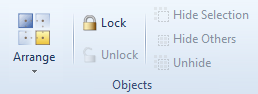
Layout area
|
As with the design area, the Lock and Unlock functions have been extended for the Layout area. They allow objects to be locked in the Layout area, so that they are safe against unintended moves, for instance. |
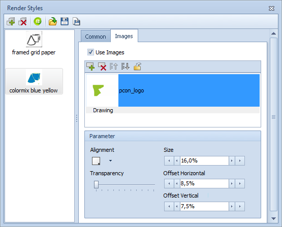
Render styles
The Render Styles dialog now allows vertical and horizontal distance to be set for images which have been assigned to a style.
The distance in question will be that from the corner or edge of the relevant view port and will be given as a percentage.
The render styles thus offer increased flexibility for the designer.